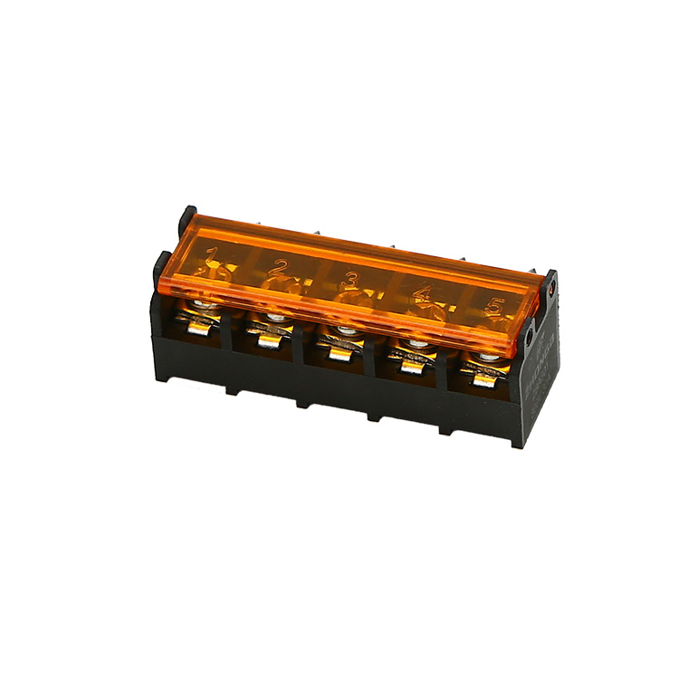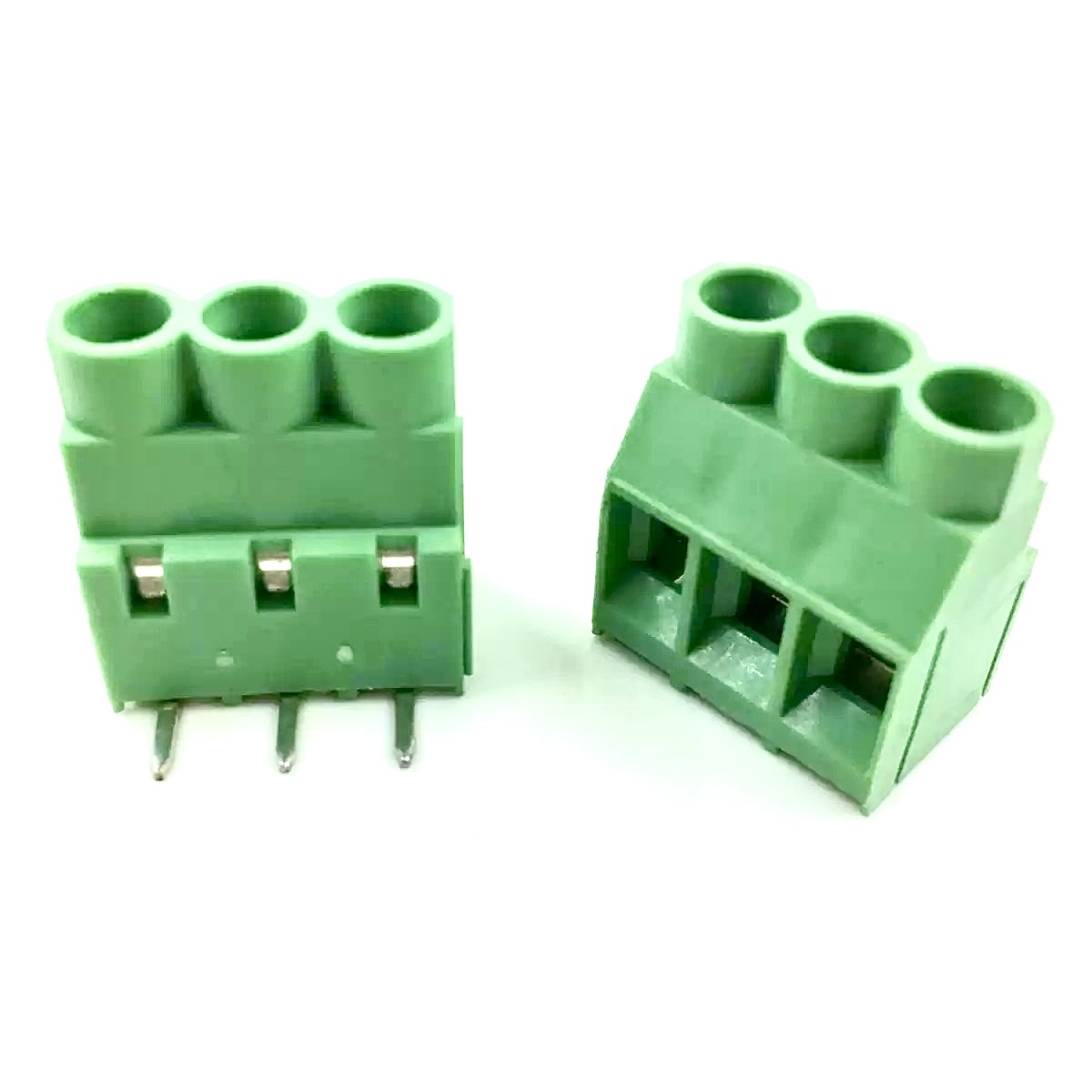

How to Connect Wire to a PCB Terminal Block
A wire is properly connected to a PCB terminal block when the specified conductor is prepared to the specified strip length, fully seated in the correct opening, secured by the terminal’s intended mechanism, and checked according to the product and equipment instructions. There is no universal strip length or screw torque that applies to every terminal block.
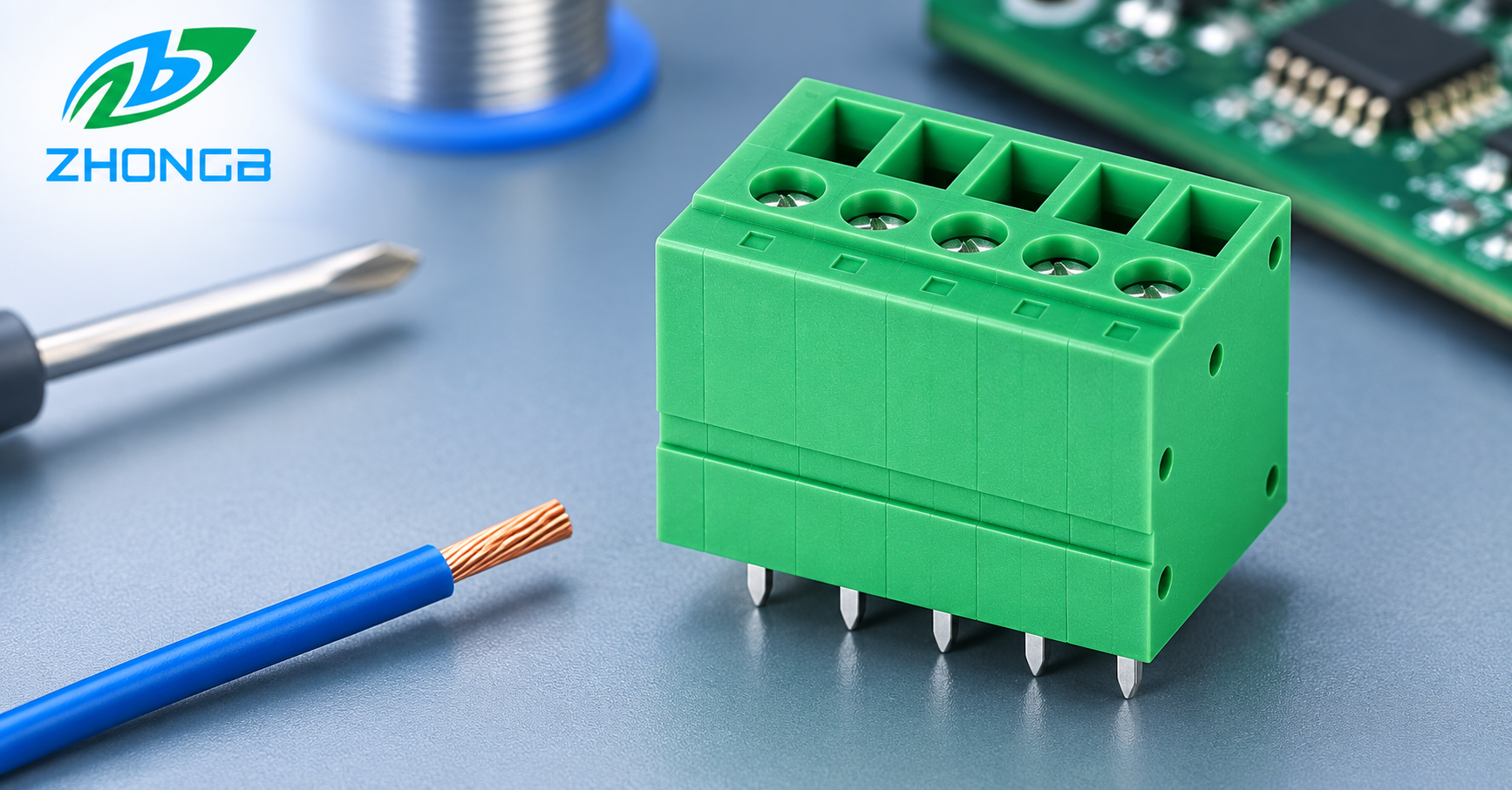
This guide covers PCB-mounted screw and spring clamp terminal blocks used in equipment such as PLC I/O modules, HVAC controllers, and LED drivers. It is written for trained people assembling or servicing equipment with the supply isolated. This guide explains how to connect wire to terminal block products mounted on a PCB, including screw and spring clamp designs.
Contents
- Check the terminal and conductor before wiring
- Prepare and connect a screw terminal
- Prepare and connect a spring clamp terminal
- Inspect the finished connection
- Choose the connection method for your equipment
- Common wiring mistakes
- FAQ
Check the Terminal and Conductor Before Wiring
The connection method is only one part of the decision. Before cutting a wire, identify these six variables for the exact terminal block and circuit:
| Variable | What to confirm | Why it matters |
|---|---|---|
| Terminal construction | Screw clamp, spring cage, push-in, or another design | The insertion and release steps differ. |
| Conductor | Copper conductor type, size, and strand construction accepted by the terminal | A wire that enters the opening may still be outside the approved range. |
| Wire-end preparation | Whether bare strands or a specified ferrule are permitted | Preparation affects how the conductor sits in the clamp. |
| Strip length | The value in the model-specific instructions | Excess exposed copper or trapped insulation can compromise the connection. |
| Electrical rating | Applicable voltage and current under the relevant rating system | The terminal must suit the circuit and installation conditions. |
| Access and retention | Tool clearance, wire exit direction, strain relief, and service access | A sound clamp cannot compensate for a wire pulled sideways by the enclosure. |
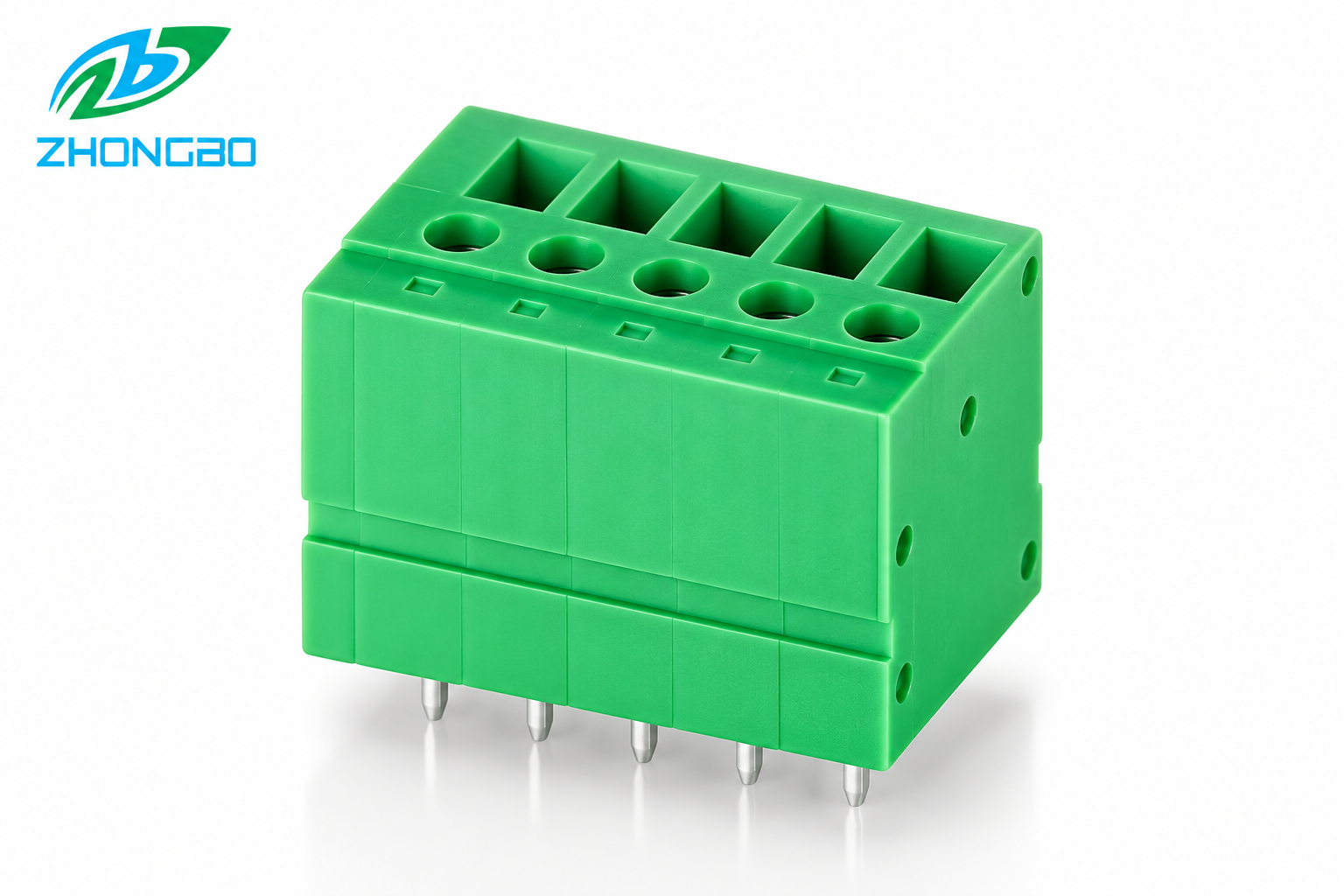
Start with the complete model number and the manufacturer’s latest datasheet, including its position count and orientation. Similar-looking terminal blocks can have different conductor ranges, strip lengths, tightening instructions, or approvals. Check the marking and documentation for the actual part supplied to production.
For a PCB assembly, also verify that the terminal is mounted and soldered as intended before applying wire-handling forces. A mechanically weak board attachment is a separate failure risk even if the conductor is firmly clamped. Where the finished equipment needs strain relief, plan it outside the terminal. Do not use the clamping point as the cable’s only mechanical support.
IEC and UL values must be read separately. A model may show different ratings or conditions of use in IEC documentation and a UL recognition record. Do not copy one figure into the other column or describe a whole product range as approved because one model has a certificate. The published scope of IEC 60947-7-4 addresses PCB terminal blocks for copper conductors; UL Solutions identifies UL 1059 among the U.S. standards used for terminal blocks. Neither source supplies the installation values for a particular Zhongbo model.
How to Connect a Wire to a PCB Screw Terminal Block
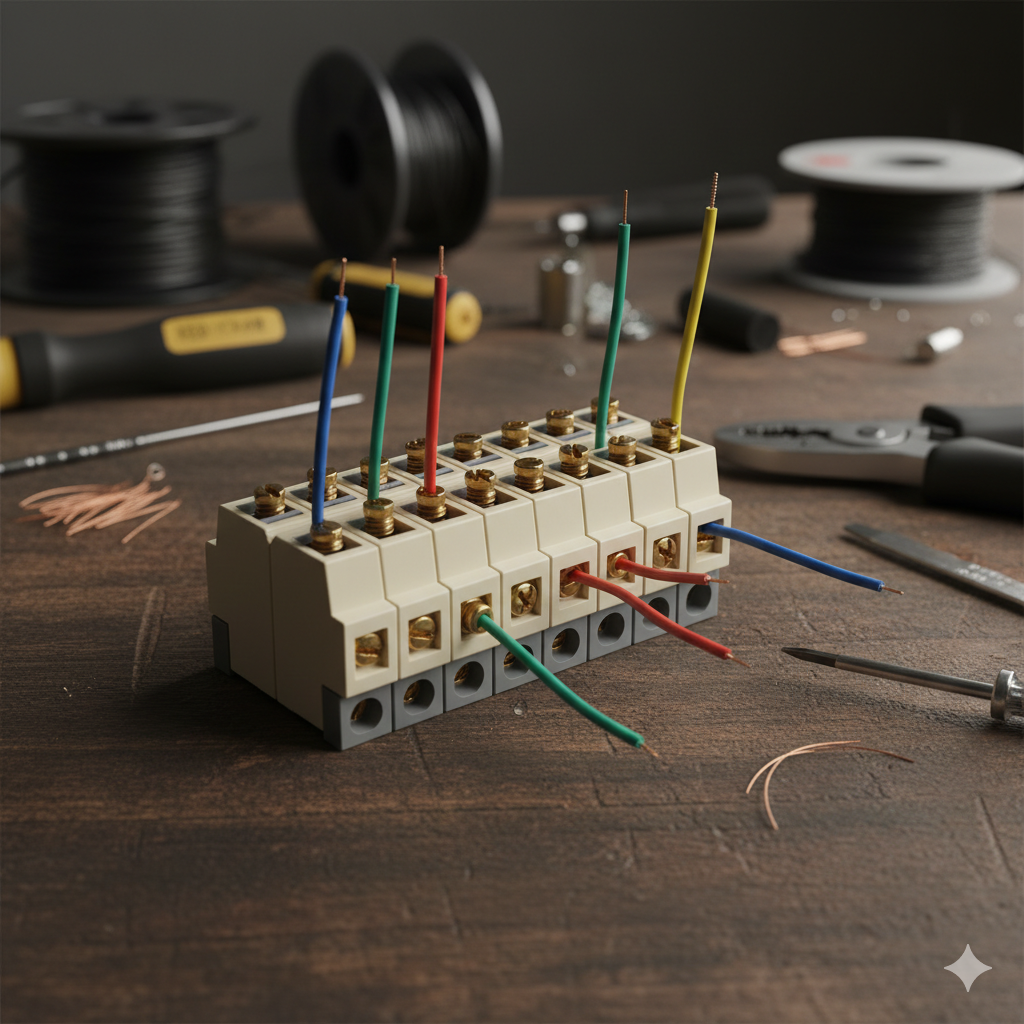
A screw terminal uses a screw-driven clamping mechanism. The exact location of the wire opening and screw, and whether a ferrule is acceptable, depend on the model. Use the drawing or installation sheet that matches the part on your bench.
1. Isolate and identify the circuit
Follow the equipment’s isolation procedure and verify that the circuit is in the required safe state. Match the board terminal position to the wiring diagram. Confirm polarity or signal assignment before inserting the conductor; a firm connection to the wrong position is still a wiring fault.
Check that the chosen wire is within the model’s stated conductor range and is of an accepted type. Look for damaged insulation, missing strands, corrosion, or a previously compressed wire end. Replace or re-prepare a conductor when its condition is uncertain.
2. Strip the wire to the model-specific length
Measure the strip length stated for that exact terminal and conductor preparation. Use a stripping tool suited to the wire size. After stripping, inspect the copper: strands should be intact and the insulation edge clean. A cut strand reduces the conductor’s effective section and can leave a loose filament near an adjacent position.
If the process calls for a ferrule, confirm that the terminal accepts that ferrule and conductor combination. Use the specified ferrule length and an appropriate crimp tool. A ferrule is not an automatic remedy for an out-of-range wire. Likewise, do not tin a stranded wire end unless the terminal instructions expressly permit it; soldered ends behave differently under a clamp.
3. Insert and secure the conductor
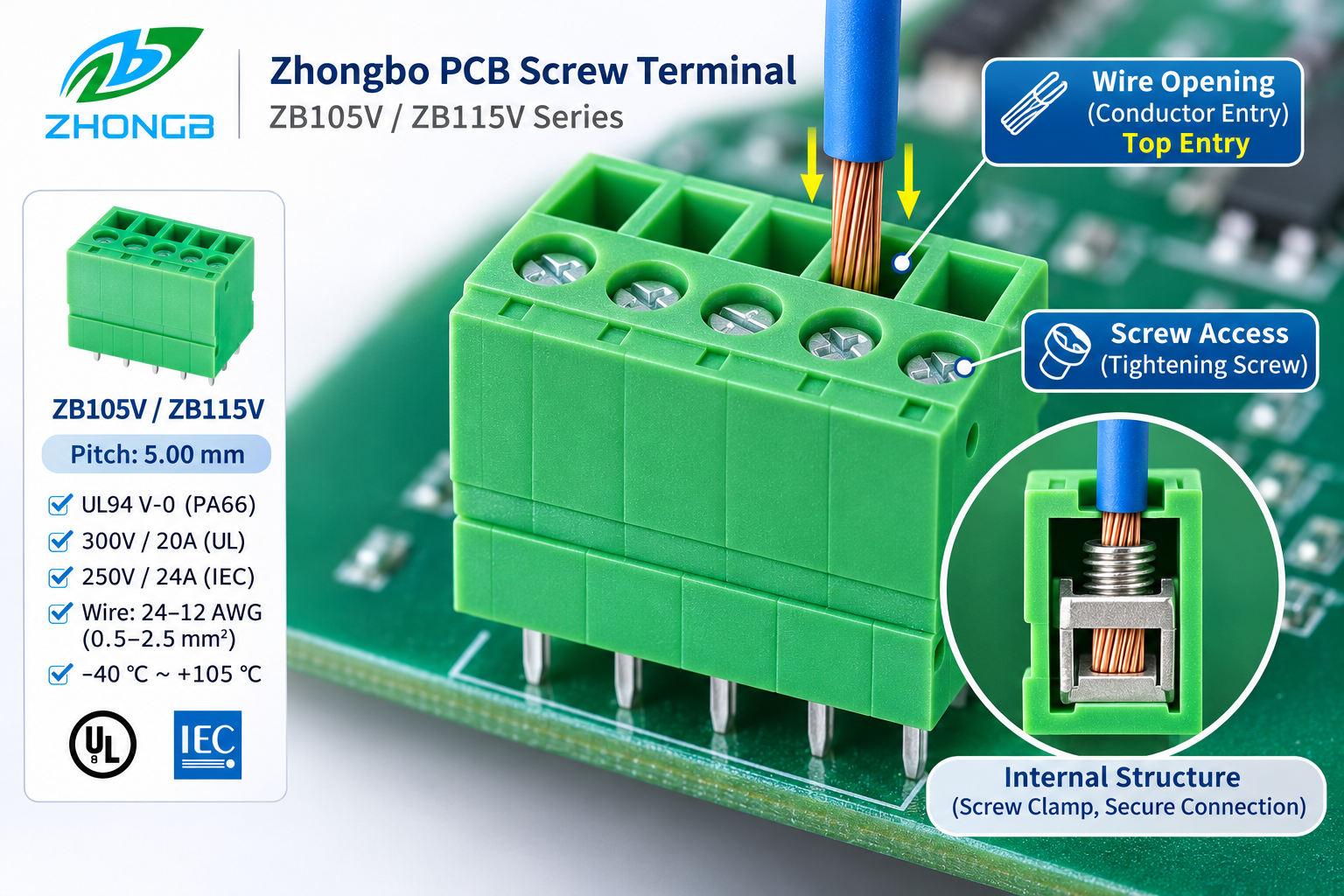
Open the clamp as directed by the manufacturer. Insert the prepared conductor into the wire entry, not the screwdriver access opening. Seat it to the intended depth without folding strands back or trapping insulation in the contact area. Keep stray copper outside adjacent terminals.
Tighten with the specified tool and, where the model gives a torque, apply that value using an appropriate controlled method. “As tight as possible” is not an instruction: excessive force can damage the screw, clamp, housing, or PCB attachment. Too little force can leave an unstable connection. If there is no verified torque available for the exact part, obtain the installation information before approving the assembly process.
4. Inspect before moving to the next position
Check that the wire follows the intended exit path and is not forced sideways by the enclosure. Confirm that no loose strand or exposed copper can reach a neighboring circuit. Use the manufacturer’s specified retention check, if one is provided, without pulling hard enough to damage the PCB. Record any required production inspection result.
How to Connect a Wire to a Spring Clamp PCB Terminal Block
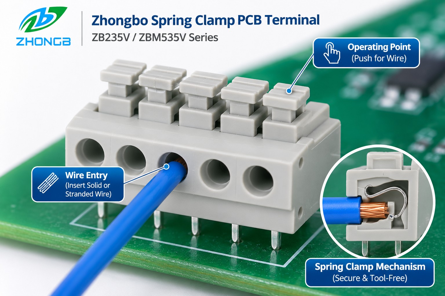
“Spring clamp” covers several mechanisms. Some require a tool to open a spring cage; others provide a lever or a push-in path for approved wire preparations. Never assume that a conductor can simply be pushed into every spring terminal.
Use the exact Zhongbo model drawing to identify the wire opening and operating point. Confirm its accepted conductor types, sizes, ferrules, and strip length. Prepare the wire as described above, then operate the clamp by the method shown for that model. Insert the conductor fully while the opening is available; release the mechanism and confirm the wire is retained. Keep the release access clear enough for future maintenance.
Spring pressure can remove a screw-tightening step from assembly, but it does not remove the need to check wire preparation or seating. A partly inserted conductor may appear attached while making poor contact. A wire or ferrule outside the approved range may also feel secure during a casual pull.
For repeated service, establish a documented removal method. Operate the designated release point before withdrawing the wire. Pulling against a closed clamp can damage the conductor or terminal. Reassess the wire end before reconnecting it.
Inspect the Finished Connection
The first inspection is visual. At each terminal position, verify that the intended conductor is in the intended circuit, the insulation ends where the terminal instructions require, and no strands escape the clamp. Check for cracked housings, damaged screws, tilted terminal bodies, stressed solder joints, or a cable path that pulls on the PCB.
Next, apply the checks required by the equipment’s production or service procedure. Depending on the circuit, these may include a documented retention check, continuity measurement while de-energized, or a system-level electrical test after reassembly. The test method and limits must come from the equipment design and applicable instructions; this article cannot set a universal pass value.
Inspect both sides of the connection when accessible. A wire may be correctly clamped while the PCB pad, solder joint, or copper trace is damaged. Likewise, a sound board connection does not prove that the conductor is fully inserted. Treat the wire-to-clamp and terminal-to-board interfaces as separate checkpoints.
If a connection fails inspection, isolate the circuit again and follow the model’s removal instructions. Do not hide an uncertain termination by tightening it repeatedly. Re-prepare the conductor or replace the component if its condition warrants it, then perform the prescribed checks again.
Which Connection Method Fits Your Equipment?
The six variables from the first table remain the decision criteria. The comparison below describes process differences, not guaranteed performance advantages of every model.
| Decision point | PCB screw terminal | Spring clamp PCB terminal |
|---|---|---|
| Assembly action | Insert conductor and tighten the screw as instructed | Open or actuate the spring mechanism, insert conductor, then release as instructed |
| Process control | May require a specified tightening torque and suitable tool | Requires correct actuation and full conductor seating |
| Service access | Screw must remain accessible | Release point must remain accessible |
| Wire preparation | Follow the model’s conductor and ferrule rules | Follow the model’s conductor and ferrule rules |
| PCB and cable layout | Allow screwdriver access and avoid side load | Allow operating-tool access and avoid side load |
| Best comparison method | Time a controlled build and test the actual assembly | Time a controlled build and test the actual assembly |
For a PLC I/O board, dense field wiring and repeated service may make tool access and labeling especially important. For an HVAC controller, installers may encounter different accepted conductor constructions, so the exact wire range deserves attention. For an LED driver, a compact enclosure can limit both screwdriver clearance and cable bend space. None of those applications alone determines whether screw or spring is correct; the complete equipment design and selected part do.
A terminal is unsuitable when the conductor falls outside its approved range, the necessary operating point becomes inaccessible after assembly, or the cable path imposes unsupported force on the connection. It is also unsuitable when the required circuit rating or documented approval for that exact model cannot be established.
Common Wiring Mistakes
Using one strip length for every terminal. Strip length belongs to the selected model and wire-end preparation. Keep it in the assembly instruction beside the part number.
Putting the conductor in the wrong opening. On compact PCB terminals, wire entry and tool access can look similar in a hurried build. Use a clear product photo and drawing in work instructions.
Assuming every ferrule is acceptable. Confirm ferrule permission and size for the specific terminal. Document the crimp method as part of the wiring process.
Placing two wires in one clamp without confirmation. The terminal must explicitly allow the number and combination of conductors used. Otherwise, select another approved distribution method.
Treating a tug as the only inspection. A tug cannot verify polarity, electrical rating, stray strands, or a damaged PCB joint.
Ignoring service access. A terminal that can be wired before enclosure assembly may be impossible to release or inspect later. Review the finished equipment, not only the open PCB.
FAQ
Can I put stranded wire directly into a screw terminal block?
Only if the exact terminal documentation permits that conductor type and size. Some connections accept bare stranded wire; others require or allow a particular ferrule. Follow the model-specific preparation instructions.
Should I always use a ferrule with spring clamp terminals?
No. The answer depends on the clamp mechanism and the manufacturer’s approved conductor combinations. Check the model’s conductor table and assembly instructions before adding a ferrule.
How much insulation should I strip?
Use the strip length specified for the exact terminal and wire preparation. There is no reliable universal value for PCB terminal blocks. Confirm it on the current datasheet or installation drawing before production.
How tight should a PCB screw terminal be?
Use the tightening instruction or torque supplied for that exact part. Avoid estimating by feel when a torque is specified. The equipment’s assembly procedure should identify the tool and inspection method.
Can I remove and reconnect the same wire?
Follow the terminal’s release instructions and inspect the removed conductor. Re-strip, re-crimp, or replace a damaged end as required by the approved process. Also check the terminal for damage before reuse.
Request a Model-Specific Wiring Check
If you are selecting a PCB terminal for a control board, send us the board drawing, conductor type and size, expected circuit rating, enclosure access constraints, and required approval market. We can help identify a candidate Zhongbo part and provide its drawing, datasheet, sample, and model-specific wiring information for your engineering review.